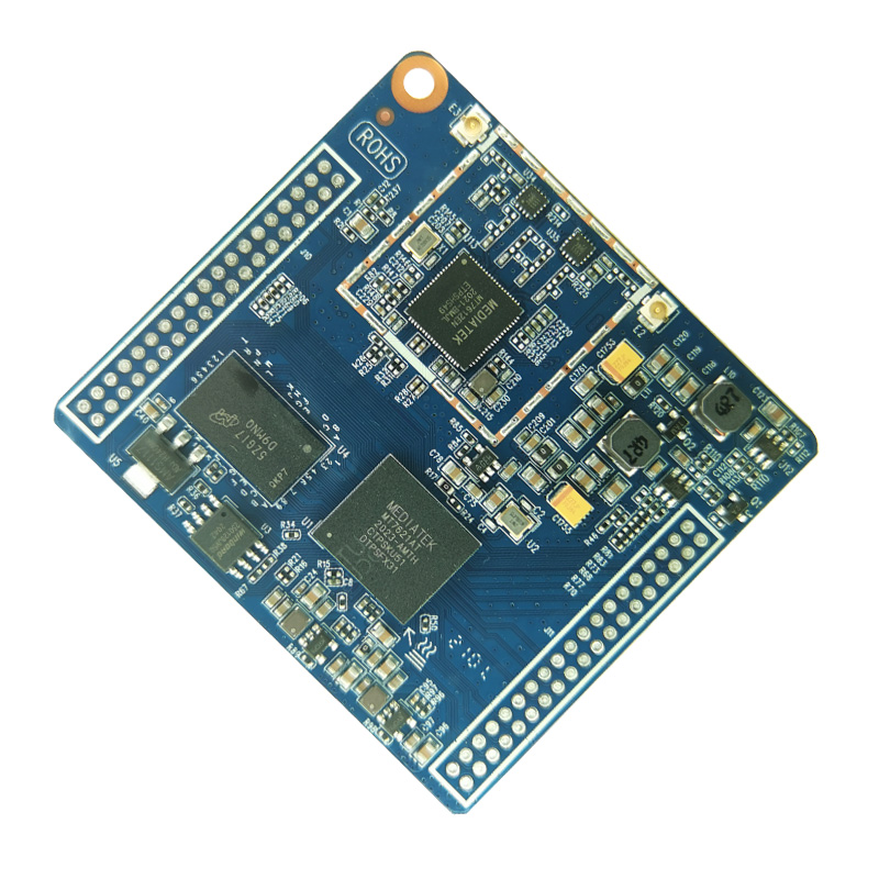

Main control chip: MT7621AT+MT7612EN
Specifications: 2T2R
Speed: 866M
Interface: USB, WAN, LAN, I2S, I2C/PCM, UART, GPIO
Size: 62*56.6mm(L*W)
Working voltage: 5V
Wireless standard: 802.11b/g/n/ac
Band width: 5.8G
Working temperature: -20°C to +85°C
Features
■ Conforms to IEEE802.11b/g/n wireless network protocol, supports three working modes of bridging, routing, and access point;
■ Adopt 2x2 MIMO (Multiple input multiple output) architecture, wireless signal multi-channel transmission and reception, the transmission rate is up to 1200Mbps;
■ Achieve a variety of communication transmission, input and output control, intelligent control of IOT applications, convenient for debugging and product development.
■ Multiple GPIOs, 1 UART interface, 1WAN, 3LAN wired network port “stamp hole” and “pin” dual design external connection method four IPEX sockets, freely configurable antenna type
■ Application areas: smart home, wireless storage, WIFI speakers, network cameras, baby monitoring, routers, repeaters, wireless APs
Module size chart
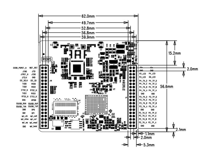
Module pin
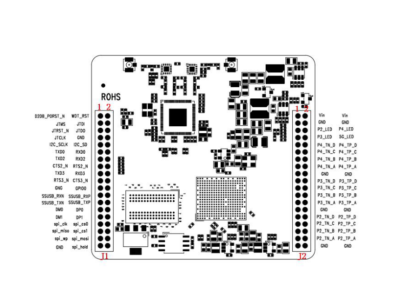
| Pin | Function | Descriptionion |
| J1 | ||
| 1 | D2DB_PORST_N | Power on reset |
| 2 | WDT_RST_N | Watchdog rese |
| 3 | JTMS | JTAG Mode Select |
| 4 | JTDI | JTAG Data Input |
| 5 | JTRST_N | JTAG Target Reset |
| 6 | JTDO | JTAG Data Output |
| 7 | JTCLK | JTAG Clock |
| 8 | GND | Ground |
| 9 | I2C_SCLK | I2C Clock |
| 10 | I2C_SD | I2C Data |
| 11 | TXD0 | RGMII2 Tx Data bit #0 |
| 12 | RXD0 | RGMII2 Rx Data bit #0 |
| l3 | TXD2 | UART TX Data |
| 14 | RXD2 | RGMII2 Rx Data bit #2 |
| 15 | CTS2_N | UART Clear To Send |
| 16 | RTS2_N | UART Request To Send |
| 17 | TXD3 | RGMII2 Tx Data bit #0 |
| 18 | RXD3 | RGMII2 Rx Data bit #3 |
| 19 | RTS3_N | UART Request To Send |
| 20 | CTS3_N | UART Clear To Send |
| 21 | GND | Ground |
| 22 | GPIO0 | GPO0 (output only) |
| 23 | SSUSB_RXN | USB Port0SS data pinRX+-(USB3.0) |
| 24 | SSUSB_RXP | USB Port0SS data pinRX+ (USB3.0) |
| 25 | SSUSB_TXN | USB Port0SS data pinTX- (USB3.0) |
| 26 | SSUSB_TXP | USB Port0 SS data pin TX+ (USB3.0) |
| 27 | DM0 | USB Port0 HS/FS/LS data pin Data- (USB3.0) |
| 28 | DP0 | USB Port0 HS/FS/LS data pin Data+ (USB3.0) |
| 29 | DM1 | USB Port1 data pin Data+ (USB2.0) |
| 30 | DP1 | USB Port1 data pin Data+ (USB2.0) |
| 31 | SPI_CIK | ND_RE_N |
| 32 | SPI_CS0 | ND_CS_N |
| 33 | SPI_MISO | ND_D4 |
| 34 | SPI_CS1 | ND_WE_N |
| 35 | SPI_WP | ND_D6 |
| 36 | SPI_MISI | ND_D5 |
| 37 | GND | Ground |
| 38 | SPI_HOLD | ND_D7 |
| J2 | ||
| 1 | VIN | POWER |
| 2 | VIN | POWER |
| 3 | GND | Ground |
| 4 | GND | Ground |
| 5 | P2_LED | Port #2 PHY LED indicators |
| 6 | P4_LED | Port #4 PHY LED indicators |
| 7 | P3_LED | Port #3 PHY LED indicators |
| 8 | 5G_LED | 5G_WIFI_LED |
| 9 | P4_TN_D | Port #4 MDI Transceivers |
| 10 | P4_TP_D | Port #4 MDI Transceivers |
| 11 | P4_TN_C | Port #4 MDI Transceivers |
| 12 | P4_TP_C | Port #4 MDI Transceivers |
| 13 | P4_TN_B | Port #4 MDI Transceivers |
| 14 | P4_TP_B | Port #4 MDI Transceivers |
| 15 | P4_TN_A | Port #4 MDI Transceivers |
| 16 | P4_TP_A | Port #4 MDI Transceivers |
| 17 | GND | Ground |
| 18 | GND | Ground |
| 19 | P3_TN_D | Port #3 MDI Transceivers |
| 20 | P3_TP_D | Port #3 MDI Transceivers |
| 21 | P3_TN_C | Port #3 MDI Transceivers |
| 22 | P3_TP_C | Port #3 MDI Transceivers |
| 23 | P3_TN_B | Port #3 MDI Transceivers |
24 | P3_TP_B | Port #3 MDI Transceivers |
| 25 | P3_TN_A | Port #3 MDI Transceivers |
| 26 | P3_TP_A | Port #3 MDI Transceivers |
| 27 | GND | Ground |
| 28 | GND | Ground |
| 29 | P2_TN_D | Port #2 MDI Transceivers |
| 30 | P2_TP_D | Port #2 MDI Transceivers |
| 31 | P2_TN_C | Port #2 MDI Transceivers |
| 32 | P2_TP_C | Port #2 MDI Transceivers |
| 33 | P2_TN_B | Port #2 MDI Transceivers |
| 34 | P2_TP_B | Port #2 MDI Transceivers |
| 35 | P2_TN_A | Port #2 MDI Transceivers |
| 36 | P2_TP_A | Port #2 MDI Transceivers |
| 37 | GND | Ground |
| 38 | GND | Ground |